mirror of
https://github.com/meshtastic/meshtastic.git
synced 2024-09-20 08:07:33 -07:00
305 lines
12 KiB
Plaintext
305 lines
12 KiB
Plaintext
---
|
|
id: serial
|
|
title: Serial Module Configuration
|
|
sidebar_label: Serial
|
|
description: This module is an interface to talk to and control your Meshtastic device over a serial port.
|
|
---
|
|
|
|
import Tabs from "@theme/Tabs";
|
|
import TabItem from "@theme/TabItem";
|
|
|
|
The serial module config options are: Enabled, Echo, Mode, Receive GPIO, Transmit GPIO, Baud Rate, Timeout, and Override Console Serial Port. Serial Module config uses an admin message sending a `ConfigModule.Serial` protobuf.
|
|
|
|
This is an interface to talk to and control your Meshtastic device over a serial port. The module can be set to different [modes](#mode), each fulfilling a different use-case.
|
|
|
|
|
|
|
|
<object data="https://www.youtube.com/embed/HdOiGKBtapw?autohide=1&autoplay=0" width="100%" height="400"></object>
|
|
|
|
## Serial Module Config Values
|
|
|
|
### Enabled
|
|
|
|
Enables the serial module.
|
|
|
|
### Echo
|
|
|
|
If set, any packets you send will be echoed back to your device.
|
|
|
|
### Mode
|
|
|
|
Defaults to 'Simple'.
|
|
|
|
Available Values:
|
|
|
|
- `DEFAULT` equals `SIMPLE`.
|
|
- `SIMPLE` operates as a dumb UART tunnel. What goes in will come out, requires a channel named 'serial'.
|
|
- `PROTO` exposes the Protobuf Client API on this serial port. You can use this to connect from another device, see the [Arduino client library](https://github.com/meshtastic/Meshtastic-arduino) and the [API Reference](/docs/development/device/client-api).
|
|
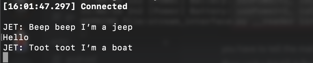
- `TEXTMSG` will allow you to send a string over the serial port to the device, which will be broadcasted as a text message to the default channel. Any text message received from the mesh will be sent to the serial port as follows: `<Short Name>: <text>`.
|
|
- `NMEA` will output a NMEA 0183 Data stream containing the internal GPS or fixed position and other node locations as Waypoints (WPL).
|
|
- `CALTOPO` will output NMEA 0183 Waypoints (WPL) every 10 seconds for all valid node locations, to be consumed by [CalTopo / SARTopo](/docs/software/integrations/caltopo.mdx).
|
|
|
|
### Receive GPIO Pin
|
|
|
|
Set the GPIO pin to the RXD pin you have set up.
|
|
|
|
### Transmit GPIO Pin
|
|
|
|
Set the GPIO pin to the TXD pin you have set up.
|
|
|
|
:::tip
|
|
Connect the TX pin to the other device's RX pin, and vice versa. Connect their grounds to each other (not necessary if they're both plugged into the same USB power source.)
|
|
:::
|
|
|
|
### Baud Rate
|
|
|
|
The serial baud rate.
|
|
|
|
### Timeout
|
|
|
|
The amount of time to wait before we consider your packet as "done".
|
|
|
|
### Override Console Serial Port
|
|
|
|
If set to true, this will allow Serial Module to control (set baud rate) and use the primary USB serial bus for output. This is only useful for NMEA and CalTopo modes and may behave strangely or not work at all in other modes. Setting TX/RX pins in the Serial Module config will cause this setting to be ignored.
|
|
|
|
:::tip
|
|
Once module settings are changed, a **reset** is required for them to take effect.
|
|
:::
|
|
|
|
## Serial Module Config Client Availability
|
|
|
|
<Tabs
|
|
groupId="settings"
|
|
defaultValue="apple"
|
|
values={[
|
|
{label: 'Android', value: 'android'},
|
|
{label: 'Apple', value: 'apple'},
|
|
{label: 'CLI', value: 'cli'},
|
|
{label: 'Web', value: 'web'},
|
|
]}>
|
|
<TabItem value="android">
|
|
|
|
#### Android
|
|
|
|
:::info
|
|
|
|
Serial Module Config options are available for Android.
|
|
|
|
1. Open the Meshtastic App
|
|
2. Navigate to: **Vertical Ellipsis (3 dots top right) > Radio Configuration > Serial**
|
|
|
|
:::
|
|
|
|
</TabItem>
|
|
<TabItem value="apple">
|
|
|
|
#### Apple
|
|
|
|
:::info
|
|
All serial module config options are available on iOS, iPadOS and macOS at Settings > Module Configuration > Serial.
|
|
:::
|
|
|
|
</TabItem>
|
|
<TabItem value="cli">
|
|
|
|
#### CLI
|
|
|
|
:::info
|
|
|
|
All serial module config options are available in the python CLI. Example commands are below:
|
|
|
|
:::
|
|
|
|
| Setting | Acceptable Values | Default |
|
|
| :------------: | :----------------------------------------------------------------------------------------------------------------------------------------------------------------------------------------------------------: | :----------------------------------: |
|
|
| serial.enabled | `true`, `false` | `false` |
|
|
| serial.echo | `true`, `false` | `false` |
|
|
| serial.mode | `DEFAULT` `SIMPLE` `PROTO` `TEXTMSG`, `NMEA`, `CALTOPO` | `DEFAULT` |
|
|
| serial.rxd | GPIO Pin Number 1-39 | Default of `0` is Unset |
|
|
| serial.txd | GPIO Pin Number 1-33 | Default of `0` is Unset |
|
|
| serial.baud | `BAUD_DEFAULT` `BAUD_110` `BAUD_300` `BAUD_600` `BAUD_1200` `BAUD_2400` `BAUD_4800` `BAUD_9600` `BAUD_19200` `BAUD_38400` `BAUD_57600` `BAUD_115200` `BAUD_230400` `BAUD_460800` `BAUD_576000` `BAUD_921600` | `BAUD_DEFAULT` (38400) |
|
|
| serial.timeout | `integer` (milli seconds) | Default of `0` corresponds to 250 ms |
|
|
| serial.override_console_serial_port | `true`, `false` | `false` |
|
|
|
|
|
|
:::tip
|
|
|
|
Because the device will reboot after each command is sent via CLI, it is recommended when setting multiple values in a config section that commands be chained together as one.
|
|
|
|
```shell title="Example:"
|
|
meshtastic --set serial.enabled true --set serial.echo true
|
|
```
|
|
|
|
:::
|
|
|
|
```shell title="Enable / Disable Module"
|
|
meshtastic --set serial.enabled true
|
|
meshtastic --set serial.enabled false
|
|
```
|
|
|
|
```shell title="Enable / Disable Echo"
|
|
meshtastic --set serial.echo true
|
|
meshtastic --set serial.echo false
|
|
```
|
|
|
|
```shell title="Set Mode"
|
|
meshtastic --set serial.mode DEFAULT
|
|
meshtastic --set serial.mode PROTO
|
|
```
|
|
|
|
```shell title="Set RXD to GPIO pin number 7"
|
|
meshtastic --set serial.rxd 7
|
|
```
|
|
|
|
```shell title="Set TXD to GPIO pin number 28"
|
|
meshtastic --set serial.txd 28
|
|
```
|
|
|
|
```shell title="Set Baud Rate"
|
|
meshtastic --set serial.baud BAUD_DEFAULT
|
|
meshtastic --set serial.baud BAUD_576000
|
|
```
|
|
|
|
```shell title="Set Timeout to 15 milli seconds"
|
|
meshtastic --set serial.timeout 15
|
|
```
|
|
|
|
</TabItem>
|
|
<TabItem value="web">
|
|
|
|
#### Web
|
|
|
|
:::info
|
|
All serial module config options are available in the Web UI.
|
|
:::
|
|
|
|
</TabItem>
|
|
</Tabs>
|
|
|
|
:::warning
|
|
GPIO access is fundamentally dangerous because invalid options can physically damage or destroy your hardware. Ensure that you fully understand the schematic for your particular device before trying this as we do not offer a warranty. Use at your own risk.
|
|
|
|
This module requires attaching a peripheral accessory to your device. It will not work without one.
|
|
:::
|
|
|
|
## Examples
|
|
|
|
Default is to use RX GPIO 16 and TX GPIO 17.
|
|
|
|
### Basic Usage
|
|
|
|
1. Enable the module by setting `serial.enabled` to `1`.
|
|
2. Set the pins (`serial.rxd` / `serial.txd`) for your preferred RX and TX GPIO pins. On tbeam boards it is recommended to use:
|
|
- RXD 13
|
|
- TXD 14
|
|
3. Set `serial.timeout` to the amount of time to wait before we consider your packet as "done".
|
|
4. (Optional) set serial.mode to `TEXTMSG` if you want to send messages to/from the general text message channel. For more specific control, use the `PROTO` mode, e.g. in combination with the [Arduino client library](https://github.com/meshtastic/Meshtastic-arduino/blob/master/examples/SendReceiveClient/SendReceiveClient.ino).
|
|
5. Connect to your device over the serial interface at `38400 8N1`.
|
|
|
|
With [tio](https://github.com/tio/tio) – `tio -e -b 38400 -f none /dev/myserialport`
|
|
|
|
6. Send a packet up to 237 bytes in length. This will get broadcasted over the default channel.
|
|
7. (Optional) Set `serial.echo` to `1` and any message you send out will be echoed back to your device.
|
|
|
|
### Interfacing PIR Sensor With External Microcontroller
|
|
|
|
The following are examples of using either a Raspberry Pi Pico or Arduino Mini Pro connected to a PIR sensor to detect motion. When motion is detected, a message is sent via serial to the T-Beam. The T-Beam transmits the message as text over the default channel by utilizing the serial module in TXTMSG mode.
|
|
|
|
#### Meshtastic Software Configuration
|
|
|
|
- Serial module enabled, mode: TEXTMSG
|
|
- GPIO Pins (For T-Beam) RX 13, TX 14
|
|
- 38400 Baud
|
|
|
|
#### Rasberry Pi Pico BOM
|
|
|
|
- A Raspberry Pi Pico running [CircuitPython](https://learn.adafruit.com/getting-started-with-raspberry-pi-pico-circuitpython)
|
|
- T-Beam V1.1 running Meshtastic
|
|
- PIR Sensor ([Adafruit Breadboard Model](https://www.adafruit.com/product/4871))
|
|
|
|
#### Raspberry Pi Pico Wiring
|
|
|
|

|
|
|
|
- TX pin 14 on the T-Beam to RX pin 2 on the Pico
|
|
- RX pin 13 on the T-Beam to TX pin 1 on the Pico
|
|
- PIR sensor Vcc and GND pins to Vcc/GND on breadboard respectively
|
|
- PIR sensor trigger line to Pico GPIO28 (Pico pin 34)
|
|
- GND pin on T-Beam to GND pin 38 on the Pico
|
|
- GND pin 38 on the Pico to breadboard ground rail
|
|
- 3V3 pin 36 on the Pico to the breadboard positive voltage rail
|
|
- Optional, to power the Pico off of the T-Beam instead of USB:
|
|
- Connect 5V pin on T-Beam to Vbus pin 40 on the Pico
|
|
|
|
#### Circuit Python Code
|
|
|
|
```python
|
|
import time
|
|
import board
|
|
import busio
|
|
import digitalio
|
|
|
|
# Setup PIR sensor on GP28
|
|
pir = digitalio.DigitalInOut(board.GP28)
|
|
pir.direction = digitalio.Direction.INPUT
|
|
|
|
# Setup serial UART connection TX/RX on (GP0/GP1)
|
|
uart = busio.UART(board.GP0, board.GP1, baudrate=38400, timeout=0)
|
|
|
|
while True:
|
|
if(pir.value == True):
|
|
uart.write(bytes("Motion Detected", "ascii"))
|
|
time.sleep(30)
|
|
time.sleep(0.5)
|
|
```
|
|
|
|
#### Arduino Mini Pro BOM
|
|
- An Arduino Mini Pro with example sketch from below uploaded to it.
|
|
- T-Beam V1.1 running Meshtastic
|
|
- PIR Sensor ([Adafruit Breadboard Model](https://www.adafruit.com/product/4871))
|
|
|
|
#### Arduino Mini Pro Wiring
|
|
|
|

|
|
|
|
- T-BEAM RX PIN 13 to TX PIN on the ARDUINO MINI
|
|
- T-BEAM TX PIN 14 to RX PINon the ARDUINO MINI
|
|
- T-BEAM PIN 3.3V to 3.3V PIN on the ARDUINO MINI
|
|
- T-BEAM PIN GND to GND PIN on the ARDUINO MINI
|
|
- ARDUINO MINI PIN 2 to OUT PIN on the PIR SENSOR
|
|
- ARDUINO MINI PIN 3.3V to 3.3V on the PIR SENSOR
|
|
- ARDUINO MINI PIN GND to GND PIN on the PIR SENSOR
|
|
|
|
#### Arduino Mini Pro Code
|
|
|
|
```cpp
|
|
int LED = 13; // the pin to which the LED is connected
|
|
int PIR = 2; // the pin to which the sensor is connected
|
|
int previousState = LOW; // previous state of the sensor
|
|
|
|
|
|
void setup() {
|
|
pinMode(LED, OUTPUT); // initialize the LED as an output
|
|
pinMode(PIR, INPUT); // initialize the sensor as an input
|
|
Serial.begin(9600); // initialize serial communication
|
|
}
|
|
|
|
void loop(){
|
|
int currentState = digitalRead(PIR); // read the current state of the sensor
|
|
if (currentState != previousState) { // check if the state has changed
|
|
if (currentState == HIGH) { // check if there is motion
|
|
digitalWrite(LED, HIGH); // turn the LED on
|
|
Serial.println("Motion Detected");
|
|
}
|
|
else {
|
|
digitalWrite(LED, LOW); // turn the LED off
|
|
Serial.println("No Motion");
|
|
}
|
|
previousState = currentState; // update the previous state
|
|
}
|
|
delay(100); // small delay to avoid false sensor readings
|
|
|
|
}
|
|
```
|